What does it take to design a building?
The final realized form of the design is seen in the creation of construction documents. Those documents can be divided into Construction Drawings and Specifications.
The Construction Drawings include all of the graphic designs and drawings, typically on large sheets of paper, and text necessary for your project to be translated into a ‘language’ that the various contractors and subcontractors can utilize in order to build or remodel the project.
The way that your architectural project is made clear to all of the parties who will both approve and build it is through the completion of a set of Construction Documents.
The Construction Documents are the ‘Bible’ for your building, typically containing drawings and specifications. The drawings are typically like those seen above, and are accomplished in a variety of ways, from the use of computer drafting programs like AutoCAD to BIM (Building Information Modeling) software such as REVIT or even hand drawings if needed. The purpose of construction drawings is to carefully show the quantity and locations of the individual elements of each design.
Specifications are typically text documents composed in a Microsoft Word or other type of format. The purpose of the specifications is to describe the quality of the work to be completed, as well as specific performance requirements as necessary.
Traditionally, Construction Drawings may consist of the following drawings:
- Site Plan – Shows the location of the building on the site relative to other features on the site. It includes elements of the plot plans.
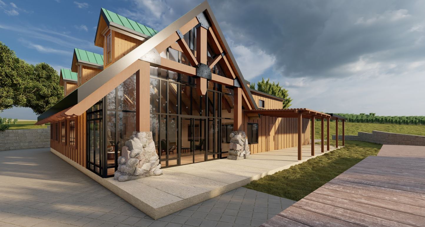
- Perspective Drawings – These show the building in 3D from the point of view of a person looking at the constructed building.
- Plot Plans – Shows the legal description of the site as well as the location of the building on the site.
- Floor Plans – Demonstrate the design / layout of the various spaces and their relationships to each other as well as any other additional design features.
- Exterior Elevations – Exhibit the exterior orthographic views of each face of the building
- Roof Plans – Looking down on the roof from a Bird’s Eye view, the roof plan shows everything you would see relevant to the covering of the spaces and their relationship to other various elements on the site.
- Sections – Seeing the construction as though a large chain saw cut through the the building at various locations, section drawings show the intended design of the building’s inner workings necessary to show the relationship between its supporting elements and structure with water protection and insulation.
- Foundation Plans – Seeing the building’s contact with the soil, the depth of grade beams and relationship with any penetrations through the slab, the foundation plans are where the construction of the building’s component parts begins.
- Framing Plans – Shows the location, spacing, frequency of structural members necessary to hold the design of the building.
- Interior Elevations – Useful for interior design, the interior elevations show the face of each wall in respective rooms for the purpose of locating various items such as lighting, outlets, vents, and other elements.
- Charts and schedules – list specific quantities and requirements of the components, such as doors and windows, that may have specific functional requirements in the building.
- Other related details – Such as mechanical, electrical, and plumbing drawings, green code requirements and the like… the other details cover everything else that may be needed for the construction of the building.
Only through having a comprehensive set of construction contract documents will your project be able to be completed in a way that minimizes problems in the construction of your building.
Let us know about your project! For a consultation meeting over the phone, contact us here today–